Capture heat at the source
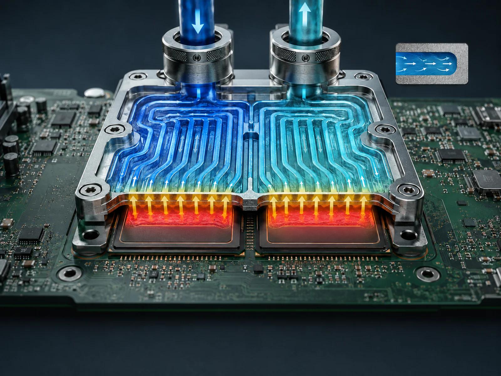
Cold plates transfer heat from CPUs, GPUs and other high-heat components into the coolant.
正在加载…

Connect heat capture, rack distribution, CDU control, and facility heat rejection around real operating conditions.
Cold plate · CDU · Rack loop · Facility interface
HOW THE SYSTEM WORKS
Cold plates, rack manifolds, CDUs and rack loops capture heat, distribute coolant, exchange heat and control operation.
Explore liquid-cooling technologyCold plates transfer heat from CPUs, GPUs and other high-heat components into the coolant.
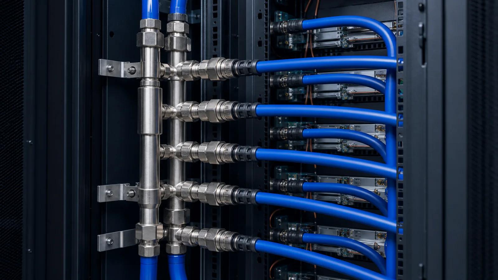
Manifolds and supply-return lines balance pressure, flow, interfaces and service access.
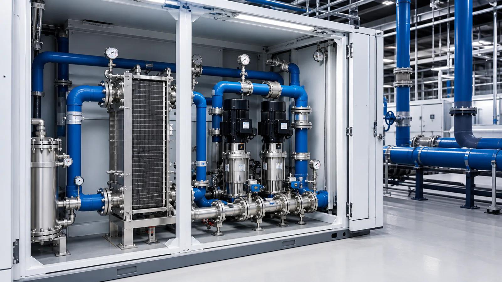
The CDU separates IT and facility loops while providing pumping, filtration and controls.
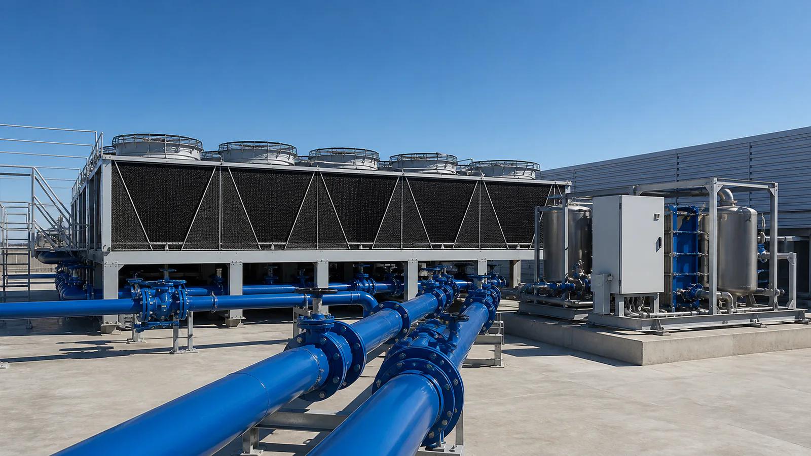
Connect the loop to chillers, dry coolers, cooling towers or heat-reuse systems.
PRODUCTS & THERMAL MANAGEMENT
Explore products, core components and engineering services for data centers, new-energy equipment and industrial applications.
View product center
A complete rack-level liquid path.
Connect cold plates, manifolds, CDUs and facility interfaces into a controlled rack loop. The system is defined around heat load, flow distribution, pressure drop, service access and operating boundaries.

Capture heat at the package interface.
Cold plates engineered around CPU and GPU heat maps, package geometry, mounting loads, material compatibility and coolant flow paths. Thermal and hydraulic behavior are verified against the actual component boundary.

Simulate the loop before it reaches the rack.
From flow-path geometry to rack distribution and facility interfaces, CFD and thermal analysis help locate pressure-drop risks, flow imbalance and hot spots before fabrication and commissioning.

Upgrade an operating site in controlled stages.
Plan the interface between new liquid loops and existing air-cooled infrastructure. Work around live operations, maintenance windows, available space, facility water and phased deployment requirements.
APPLICATION SCENARIOS
AI, HPC, cloud and colocation, live-site retrofit, new energy, industrial equipment and edge computing.
Explore all scenarios
For training clusters and online inference racks, with system boundaries defined by sustained heat load, concurrency changes and service windows.
Explore scenario
For research and engineering clusters that need stable supply-and-return conditions across long, highly utilized compute cycles.
Explore scenario
For adding high-density compute zones to shared cloud and colocation facilities while planning capacity, redundancy, metering and phased growth.
Explore scenario
Introduce liquid-cooled racks in phases while existing services remain live, coordinating space, work windows and the current cooling system.
Explore scenario
For rack-scale accelerated platforms and large AI clusters, coordinating node loads, rack loops, CDU fleets and facility heat rejection.
Explore scenario
For traction batteries, storage cabinets and fast-charging power modules, with cooling designed around uniformity, space, environment and safety boundaries.
Explore scenario
For lasers, semiconductor equipment, power electronics and continuous-duty machines, tailored around heat sources, precision, environment and service needs.
Explore scenario
For edge servers, communications equipment and distributed compute nodes, balancing cooling, acoustics, service and reliability in compact and varied environments.
Explore scenarioNEWS & INSIGHTS
Read GOTCOOL company news, product updates, liquid-cooling articles and industry insights.
View all news
Build evidence from component, node, rack and system tests, then include installation, flushing, filling and loaded acceptance in delivery.
Read article
Turn dew point, leakage, blockage, loss of flow, power and communications into detectable and recoverable control behavior.
Read article
Liquid-cooling reliability depends on the complete wetted-material system and long-term fluid management, not one material name.
Read articleENERGY SCENARIO
Adjust IT load, current PUE and electricity price to compare illustrative annual energy differences.
Results are illustrative only and do not constitute a performance commitment or quotation. Recalculate against actual project boundaries.Formula: IT load × 8,760 × (current PUE − 1.15).
PROJECT CONDITIONS
Share heat load, liquid heat-capture target, coolant conditions, facility interfaces, redundancy, and service requirements so the system boundary and validation path can be defined.